Basler
Before using a Basler camera, the software ‘Basler_pylon_8.0.2.16314’ must be installed for ‘Developer’. The ‘Basler_pylon_8.0.2.16314.exe’ must be executed as administrator. Before installation, check whether the maximum number of installable filter drivers has already been reached. The ‘pylon GigE Vision Driver’ must be activated on all LAN adapters with a Basler camera. After installation, the PC must be restarted before a Basler camera can be used in Viper.NET.
General settings
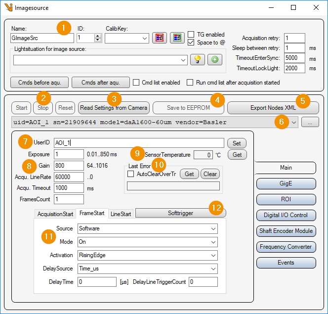
General Settings: Image Source Editor
Cancel all acquisition: Aborts a running or pending image acquisition of this image source (stops the StreamGrabber). Useful when an acquisition hangs – e.g. because the camera is waiting for a trigger that never arrives. (Replaces the former ‘Start’/’Stop’/’Reset’ buttons, which have had no function since Pylon 6.)
Read Settings from Camera: Read all parameters from the camera and assign them to this image source or image acquisition parameter set.
Export Device Parameters: Exports all parameters of the connected camera into a selectable folder. Four Pylon Feature Stream files (*.pfs) are written – for ‘CameraDevice’, ‘CameraInstance’, ‘StreamGrabber0’ and ‘DeviceTransportLayer’ – each with a timestamp and the serial number in the file name (e.g.
20260728_153000_sn_21909644_CameraDevice.pfs). The.pfsfiles can be re-imported, e.g. in the Basler pylon Viewer.Camera list: Selection list of all Basler cameras. The list can be updated with the ‘… - button’ to update the list.
Shutter Mode: Shutter mode of the sensor (e.g. ‘Global’ or ‘Rolling’). Default value for newly added cameras: ‘Global’. If the connected camera does not support the mode (e.g. line-scan or rolling-shutter sensors), the setting is ignored without error.
User ID: Camera name, which is stored in the camera by clicking on the button ‘set’.
Pixel Format: Selection of the pixel format. The list contains only the formats that the connected camera can actually set:
Mono8 / Mono12: Greyscale (Mono12 is delivered as a 16-bit image).
Bayer formats (colour cameras only, only the sensor’s native pattern, 8-bit): for delivery see Deliver colour image (item 16).
Camera colour formats (e.g. ‘RGB’, ‘YUV422’, if the camera offers them): delivered directly as a colour image (CogImage24PlanarColor).
Processed Raw: Selectable only for Bayer (raw) formats. Enables the camera’s internal colour processing of the raw image (visibly more saturated image). Default value for newly added cameras: on. Note: this is colour processing, not noise reduction.
Deliver colour image: Bayer formats only.
Off (default): The raw Bayer mosaic is delivered in a greyscale image and de-bayered downstream (Cognex/Halcon) – the previous, backward-compatible behaviour.
On: The image source de-bayers itself and delivers a colour image (CogImage24PlanarColor) directly; a downstream de-bayer step is no longer needed.
SensorTemperature: Value of the camera’s temperature sensor in [°C]. (If the feature ‘TemperatureAbs’ is not available or the camera is not connected, the value 0.0 is displayed).
Last Error: Read out and display the last error that occurred from the camera with ‘Get’ or clear it with ‘Clear’. If ‘AutoClearOverTr’ is activated, the ‘Camera over-triggered’ error is automatically cleared.
Exposure: Exposure time in [ms]. Default value for newly added cameras: 25 ms. (On line-scan cameras the exposure time applies per line and thus limits the maximum line rate.)
Gain: Analog gain factor (brightness). Default value for newly added cameras: 1.
Acqu. LineRate: Frequency in [Hertz = 1/s] at which the lines of an image are captured when line trigger mode is disabled. This parameter is only available for line scan cameras.
Acqu. Timeout: Maximum image acquisition time in [ms].
FramesCount: For line scan cameras, the image can be split into multiple ‘Frames’. The camera is then operated in ‘MultiFrame-Mode’ and sends the image in several frames. The Viper.NET image source then copies these individual image buffers into a Cognex image buffer.
Skip Lines: Number of lines to be discarded at the start of an image (line-scan cameras only). The first n lines are not included in the delivered image; the image is correspondingly n lines shorter. This can be used, for example, to hide initial, still-invalid lines right after acquisition start.
Digital Shift: Digital brightness increase via bit shift (multiplication of the pixel values by 2^n). Among other things, this allows the exposure time to be reduced (helpful against over-triggering on line-scan cameras). Values outside the range supported by the camera are clamped automatically.
Binning: Combining of neighbouring pixels, adjustable separately for horizontal and vertical (factor), with mode:
Sum: Pixel values are added (image becomes brighter).
Average: Pixel values are averaged (brightness is preserved).
Note
Binning reduces the resolution according to the factor (typical line-scan use case: 2048 → 1024 pixels).
Trigger Settings: Depending on the camera type (area or line), the following triggers must be set:
AcquisitionStart : Trigger to start a new image acquisition for a line scan camera.
FrameStart : Trigger to start a new image acquisition for an area scan camera, or a new frame of an image for a line scan camera.
LineStart : Trigger for recording a line with a line scan camera.
Softtrigger: Trigger all activated ‘Softwaretrigger’ (AcquisitionStart, FrameStart, LineStart).
Gigabit Ethernet Settings
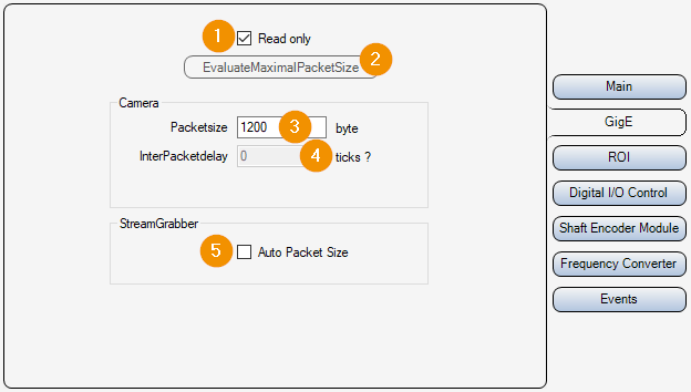
Read only:
On : Parameters 3 and 4 are only read out and displayed, but not changed.
Off : Parameters 3 and 4 can be set and changed.
Evaluate maximum packet size: Uses ‘ProbePacketSize’ to determine the largest packet size that the network path (camera ↔ LAN adapter/switch) carries end to end, and sets ‘GevSCPSPacketSize’ to that value. Works regardless of the ‘Read only’ checkbox.
Packetsize: Packet size in [byte] for the transmission of the UDP packets of the image data.
InterPacketdelay: Waiting time in [Ticks : Converted time in [µs] is displayed next to the input field] between sending individual UDP data packets of the image data. This slows down the image data transmission and avoids possible data packet collisions or an “overrun” of the LAN adapter or the PC.
Auto Packet Size: The camera automatically negotiates the maximum UDP packet size with the LAN adapter.
Adjust packet size on connect: On connect, the maximum packet size supported by the network path is negotiated automatically (like 2, but automatically on every connection). Default value for newly added cameras: on; disabled for existing projects (unchanged behaviour). On stations with several cameras on a shared LAN adapter, the option can be disabled per camera.
ROI settings
Here, an image section (ROI = Region Of Interest) can be set. This means that the entire camera chip is no longer read out and transmitted.
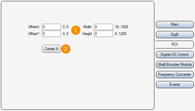
ROI Enabled: Activates the configured image section (ROI). If the option is disabled, the entire sensor area is read out and transferred.
Center X: The ‘OffsetX’ is set so that the image section is in the middle of the line. The previously set ‘OffsetX’ is also taken into account and can be set to ‘0’ beforehand. [Formula: OffsetX_new = (SensorWidth + OffsetX_alt - Width) / 2]
OffsetX/Y, Widht/Height: Selected image area. Position of the upper left corner, width and height.
Display Finder: With the DisplayFinder, a display can be selected via drag & drop for interactively setting the image section. A rectangle is then shown in that display; ‘Apply ROI from rectangle’ adopts this rectangle as the ROI (offset and size).
White balance
On colour cameras a white balance can be performed. On mono cameras the ‘White Balance’ tab is disabled, because the camera does not provide any white-balance parameters.
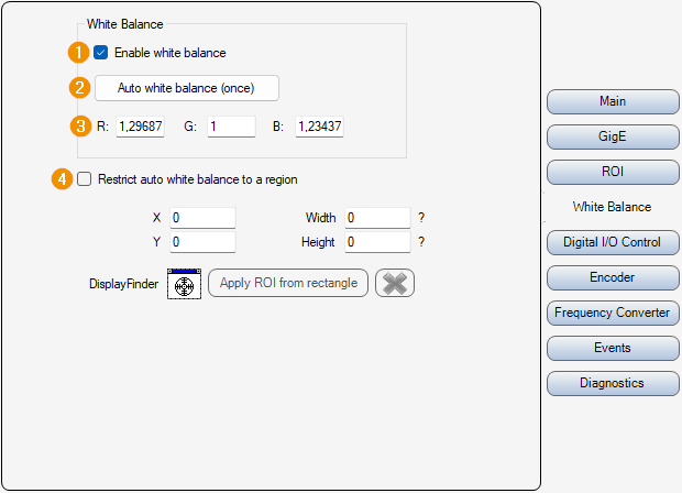
Enable white balance: Live switch for the white balance.
On: The stored R/G/B ratios are written to the camera immediately.
Off: The camera is reset to neutral (1.0), the image returns to its unbalanced state. The stored ratios are kept and are re-applied when it is enabled again.
The setting is persistent and is re-applied when the camera is connected.
Auto white balance (once): Starts the camera’s internal automatic white balance (once). The camera determines the ratios from the next acquired images – therefore a job must be running or Live must be active so that images are delivered. On completion, the determined R/G/B ratios are adopted into the fields and ‘Enable white balance’ is activated automatically.
R / G / B: Manual ratios of the colour channels. Changes take effect in the image immediately, provided ‘Enable white balance’ is active.
Restrict auto white balance to a region: Restricts the automatic white balance to an image section.
X / Y / Width / Height: Image section in which the automatic white balance is evaluated.
DisplayFinder / Apply ROI from rectangle: With the DisplayFinder, a display can be selected via drag & drop for interactively selecting the image section; Apply ROI from rectangle adopts the rectangle drawn there.
Note
For a good result, the camera should look at a grey or white, evenly illuminated surface during the automatic white balance.
Inputs Outputs
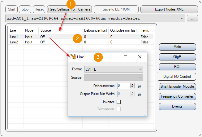
Read Settings from Camera: Read all parameters including input/output settings from the camera and update the list of available inputs/outputs (2).
IO List: List of available inputs and outputs of the camera. Double-click on an element to open the settings of the input or output (3).
Input-Output Parameters:
Format: Type of electrical input/output.
Format
Description
NoConnect
Not connected
OptoCoupled
Optically decoupled
OpenDrain
Output switches the voltage through to the consumer
TTL
Transistor transistor logic input/output with 5 volts
LVTTL
Transistor transistor logic input/output with 3.3 volts
Source: Signal with which the output is switched on/off.
Debouncetime: Input debounce time in [µs].
Output Pulse Min Width: Minimum duration of a pulse at the output in [µs].
Inverter: Invert logic of the electrical signal.
Termination: Line termination.
Input signal encoder
For line scan cameras, path-controlled triggering of the individual lines can be performed via the camera’s encoder. The trigger source for ‘LineStart’ must be set to ‘ShaftEncoderModuleOut’.
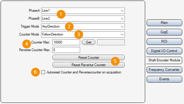
Encoder Inputs: Inputs of the camera used for phases A and B of the encoder.
Trigger Mode:
AnyDirection : The trigger signal is triggered in both directions, forward and backward.
ForwardOnly: As long as the down counter is greater than zero, the trigger signal is suppressed.
Counter Mode:
FollowDirection: Counter is incremented on forward movement and decremented on backward movement.
IgnoreDirection: Counter is incremented on forward movement and on backward movement.
Counter Max: Maximum values for the encoder counter [0..32767]. If this is exceeded, the counter starts again at ‘0’. With ‘get’ the current encoder counter value can be read out.
Reset Counter: Reset encoder counter value to ‘0’.
Autoreset Counter on acquisition: Reset the encoder counter and the down counter to ‘0’ before each start of an image acquisition.
Frequency converter
Via the frequency converter the camera can be triggered with a different frequency than the frequency of the input signal. The source of the frequency converter can be one of the inputs of the encoder (’Line1/2/3’).
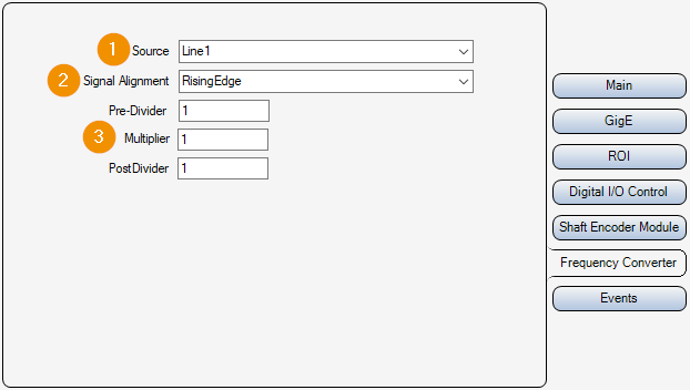
Source: Input or source for the frequency converter.
Signal Alignment:
RisingEdge: Rising Edge
FallingEdge: Falling edge
Signal Converter Parameters: The frequency converter has three modules which are applied one after the other (divider -> multiplier -> divider).
Pre-Divider: Factor by which the input frequency is reduced.
Multiplier: Factor by which the frequency is increased.
PostDivider: Factor by which the frequency is reduced.
Camera events
Camera events can be activated for analysis purposes. If an activated camera event occurs, the name of the event is written as ‘Warning’ in the ‘Gefasoft.MAK.Vision.GigEBaslerPylon’. log
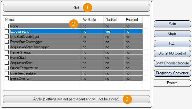
Get: Read event settings from the camera and update the list (2).
Event List: List of all Basler Pylon camera events.
Name: Name of the event.
Available: Indicates whether the event is available on the connected camera or not.
Desired: Indicates whether the user has tried to activate this event, regardless of whether it is available on the connected camera or not.
Enabled: Indicates whether this event is enabled.
Apply: Activates all events that are selected via the list checkbox (2). This setting is not permanent and is not saved. The events are only activated temporarily for analysis purposes.
Diagnostics
On the ‘Diagnostics’ tab, the monitoring of over-triggered lines (trigger overrun) can be enabled for line-scan cameras. A trigger overrun occurs when a new ‘LineStart’ trigger arrives before the camera has finished acquiring the previous line. The affected line is then discarded (lost line), which can result in a compressed or distorted image.
Note
This function is only available for line-scan cameras that support the ‘LineTriggerIgnoredCounter’ camera chunk. If a connected camera does not support it, the group is disabled.
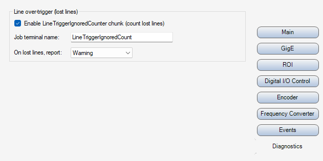
Enable LineTriggerIgnoredCounter chunk (count lost lines): Enables the ‘LineTriggerIgnoredCounter’ camera chunk, which counts the lines discarded due to over-triggering. For each image acquisition, the number of lines lost during this image (delta relative to the previous image) is determined.
Job terminal name: Name of the ‘JobInputDataBlock’ terminal that receives the number of lines lost in the current image (delta). The value can be processed further in the job (e.g. good/bad evaluation). A value of ‘0’ means that no line was lost during this image. Default: ‘LineTriggerIgnoredCount’.
On lost lines, report: Severity with which lost lines are written to the log.
Warning: Lost lines are logged as a warning.
Error: Lost lines are logged as an error.
Note
When the function is enabled (or when the camera is (re)connected), the camera’s trigger counters are reset by software, so that a correct delta (baseline = 0) can already be determined for the first image. Only if the camera does not support resetting the counter is no reference value (baseline) available for the first image. In that case the cumulative counter value is reported as a conservative worst case, so that an inspecting system reacts safely and does not rate a potentially faulty first image as good.
Configuration in the job
The value configured under Job terminal name is fed into the job via the JobInputDataBlock. For the counter value to be available in the image processing, an output terminal must be created in the CogToolBlock named JobInputDataBlock:
Name: Must exactly match the name configured under Job terminal name (default: LineTriggerIgnoredCount).
Type: System.Int32 (the value is written as an integer; if the terminal type does not match, the value is discarded and a warning is logged).
ForceChangedEvent: should be enabled so that downstream queries (e.g. in the CogDataAnalysisTool) do not return an error because of results that have not been updated.
With every image acquisition, this terminal is set to the number of lines lost in the current image (delta) and can then be processed further within the toolgroup (e.g. comparison against a limit value for a good/bad evaluation).
Important
The value of the JobInputDataBlock terminal is only updated after the actual image acquisition. If the image is acquired within the job (e.g. because the axis is controlled by the image processing), the evaluation (e.g. CogDataAnalysisTool) must therefore take place after the image acquisition.
Typical job sequence when the image is acquired within the job with axis control by the image processing:
JobInputDataBlock: passes on the terminal with the over-triggering information.
GetPos / GoToPos: controls the axis.
StartAcquisition / GetImage: starts the image acquisition or acquires the image.
CogDataAnalysisTool: evaluates the over-triggering information of the most recently acquired image after acquisition.
Hint
Each camera object should be given a descriptive name so that the messages can be clearly assigned in the log and in the job.
Note
The terminal is optional. If no matching terminal exists in the JobInputDataBlock, the value is simply not delivered (no error). Stations that do not need the evaluation therefore do not have to create the terminal.