Gefasoft Lucon
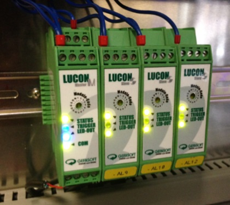
Gefasoft Lucon is a modular lighting controller with 1 to 16 lighting channels. The supply voltage is 10 - 40V. The output voltage on the channel is 0.7 - 35V. The output current is up to 1.6A per channel.
Controller settings
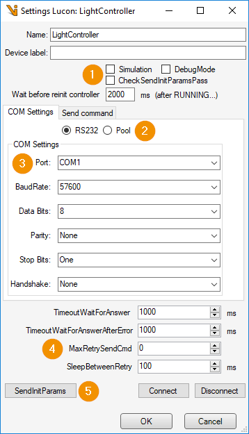
Initialization parameters
Simulation: Simulation mode.
Debug Mode: In debug mode, debug information is sent from the Lucon and written to the log by the Lumos.
CheckSendInitParamsPass: The output current can only be set if all channel initialization parameters (e.g. maximum current) could be sent.
Wait before reinit controller: The Lucon sends a “RUNNING” after switching on. The channel initialisation parameters are then sent again after the waiting time in [ms].
COM Mode
RS232: Lucon Master with RS232 interface.
Pool: Lucon Master with LAN interface. The communication is done via a stream from the Viper.NET Connection Pool (Streams and Protocols).
COM Settings: RS232 communication settings, for COM Mode RS232.
Communication behavior: Settings for the communication behavior.
Timeout wait for answer: Maximum waiting time for the command response from the Lucon.
Timeout wait for answer after error: Maximum wait time for the command response from the Lucon if an error command was received.
Max retry send cmd: Maximum send retries if the Lucon does not respond, or an error is received.
Sleep between retry: Waiting time in [ms] between the send retries.
SendInitParams: Send channel initialization parameters.
Send Command
Any commands can be sent to the Lucon master here.
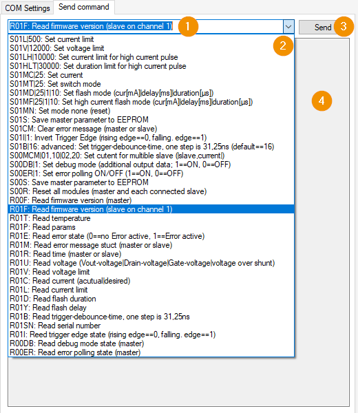
Command: Input field for the command to be sent. The text is sent up to the first colon.
Command List: Suggested list for Lucon commands in the format “Command : Description”.
Send: Send the command specified in (1).
Response: The response from the Lucon is displayed here.
Light channel settings
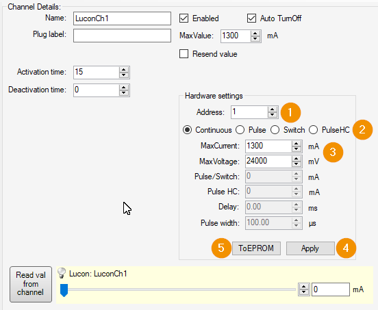
Address: Address of the light channel (Lucon slaves) [1..16].
Operation mode
Continuous: Channel in continuous operation.
Pulse: Channel in trigger mode. The lighting is pulsed via the input on the slave.
Switch: Channel in switch mode. The lighting is switched on and off via the input on the slave.
PulseHC: Channel in high current trigger mode. The lighting is pulsed via the input on the high current slave.
Channel parameters
MaxCurrent: Maximum current. (Hardware limit)
MaxVoltage: Maximum output voltage. To prevent overheating of the Lumos it is strongly recommended to adjust the maximum output voltage to the connected lighting.
Pulse/Switch: Current for Pulse/Switch mode.
Pulse HC: Current for high current pulse mode.
Delay: Pulse delay in [ms].
Pulse width: Pulse width in [ms].
Apply: Apply settings and send to Lucon.
ToEPROM: Save current settings in the EPROM of the Luconslave.