Basler
Before using a Basler camera, the software ‘Basler_pylon_6.1.0.19674’ must be installed for ‘Developer’. The ‘Basler_pylon_6.1.0.19674.exe’ must be executed as administrator. Before installation, check whether the maximum number of installable filter drivers has already been reached. The ‘pylon GigE Vision Driver’ must be activated on all LAN adapters with Basler camera. After installation, the PC must be restarted before a Basler camera can be used in Viper.NET.
General settings
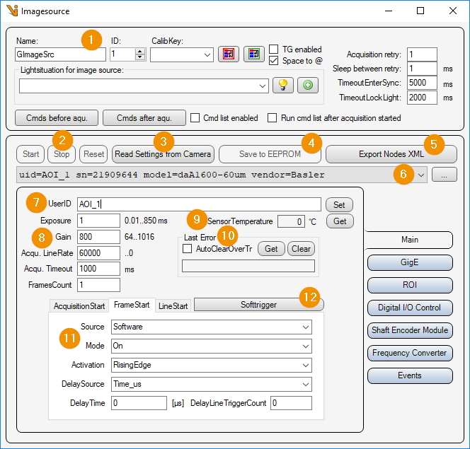
General Settings: Image Source Editor
Start/Stop/Reset
Start/Stop: These buttons are without function from Pylon 6 onwards. The ‘AcquisitionStart/Stop command’ is called by the image source with every image acquisition.
Reset: Reset all camera parameters to factory defaults. This function is currently not available in Viper.NET, because ‘Gige_Camera_restoreFactoryDefaults()’ is no longer available in Pylon 6. Instead, only the current parameters are read from the camera.
Read Settings from Camera: Read all parameters from the camera and assign them to this image source or image acquisition parameter set.
Save to EEPROM: Save current parameter set to the EEPROM of the camera. This function is currently not available in Viper.NET, because ‘Gige_Camera_writeEEPROM()’ is no longer available in Pylon 6.
Export Nodes XML: Read all parameters from the connected camera and export them to an XML file.
Camera list: Selection list of all Basler cameras. The list can be updated with the ‘… - button’ to update the list.
User ID: Camera name, which is stored in the camera by clicking on the button ‘set’.
Image acquisition:
Exposure: Exposure time in [ms].
Gain: Analog gain factor (brightness).
Acqu. LineRate: Frequency in [Hertz = 1/s] at which the lines of an image are captured when line trigger mode is disabled. This parameter is only available for line scan cameras.
Acqu. Timeout: Maximum image acquisition time in [ms].
FramesCount: For line scan cameras, the image can be split into multiple ‘Frames’. The camera is then operated in ‘MultiFrame-Mode’ and sends the image in several frames. The Viper.NET image source then copies these individual image buffers into a Cognex image buffer.
SensorTemperature: Value of the camera’s temperature sensor in [°C]. (If the feature ‘TemperatureAbs’ is not available or the camera is not connected, the value 0.0 is displayed).
Last Error: Read out and display the last error that occurred from the camera with ‘Get’ or clear it with ‘Clear’. If ‘AutoClearOverTr’ is activated, the ‘Camera over-triggered’ error is automatically cleared.
Trigger Settings: Depending on the camera type (area or line), the following triggers must be set:
AcquisitionStart : Trigger to start a new image acquisition for a line scan camera.
FrameStart : Trigger to start a new image acquisition for an area scan camera, or a new frame of an image for a line scan camera.
LineStart : Trigger for recording a line with a line scan camera.
Softtrigger: Trigger all activated ‘Softwaretrigger’ (AcquisitionStart, FrameStart, LineStart).
Gigabit Ethernet Settings
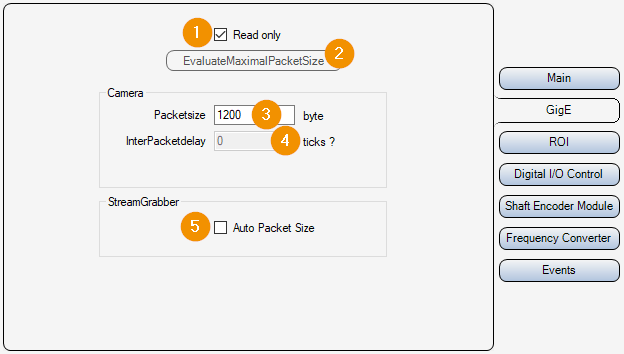
Read only:
On : Parameters 3 and 4 are only read out and displayed, but not changed.
Off : Parameters 3 and 4 can be set and changed.
EvaluateMaximalPacketSize: This function is currently unavailable in Viper.NET because ‘Gige_Camera_evaluateMaximalPacketSize()’ is no longer present in Pylon 6. Instead the current value of the parameter ‘GevSCPSPacketSize’ is displayed.
Packetsize: Packet size in [byte] for the transmission of the UDP packets of the image data.
InterPacketdelay: Waiting time in [Ticks : Converted time in [µs] is displayed next to the input field] between sending individual UDP data packets of the image data. This slows down the image data transmission and avoids possible data packet collisions or an “overrun” of the LAN adapter or the PC.
Auto Packet Size: The camera automatically negotiates the maximum UDP packet size with the LAN adapter.
ROI settings
Here, an image section (ROI = Region Of Interest) can be set. This means that the entire camera chip is no longer read out and transmitted.
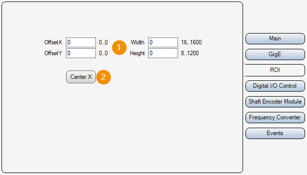
OffsetX/Y, Widht/Height: Selected image area. Position of the upper left corner, width and height.
Center X: The ‘OffsetX’ is set so that the image section is in the middle of the line. The previously set ‘OffsetX’ is also taken into account and can be set to ‘0’ beforehand. [Formula: OffsetX_new = (SensorWidth + OffsetX_alt - Width) / 2]
Inputs Outputs
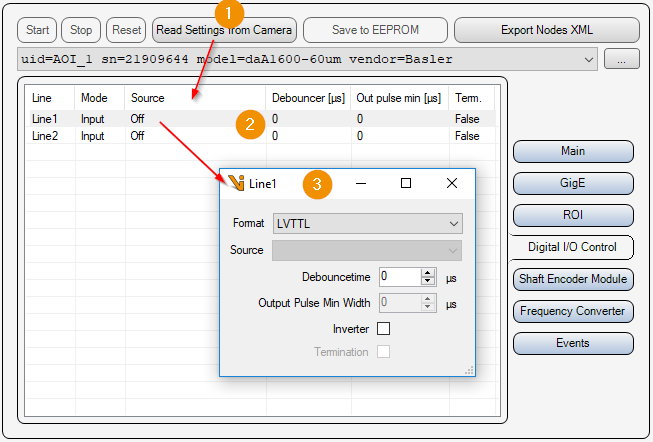
Read Settings from Camera: Read all parameters including input/output settings from the camera and update the list of available inputs/outputs (2).
IO List: List of available inputs and outputs of the camera. Double-click on an element to open the settings of the input or output (3).
Input-Output Parameters:
Format: Type of electrical input/output.
Format
Description
NoConnect
Not connected
OptoCoupled
Optically decoupled
OpenDrain
Output switches the voltage through to the consumer
TTL
Transistor transistor logic input/output with 5 volts
LVTTL
Transistor transistor logic input/output with 3.3 volts
Source: Signal with which the output is switched on/off.
Debouncetime: Input debounce time in [µs].
Output Pulse Min Width: Minimum duration of a pulse at the output in [µs].
Inverter: Invert logic of the electrical signal.
Termination: Line termination.
Input signal encoder
For line scan cameras, path-controlled triggering of the individual lines can be performed via the camera’s encoder. The trigger source for ‘LineStart’ must be set to ‘ShaftEncoderModuleOut’.
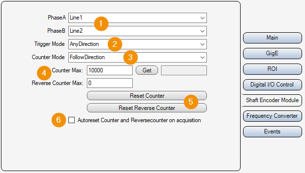
Encoder Inputs: Inputs of the camera used for phases A and B of the encoder.
Trigger Mode:
AnyDirection : The trigger signal is triggered in both directions, forward and backward.
ForwardOnly: As long as the down counter is greater than zero, the trigger signal is suppressed.
Counter Mode:
FollowDirection: Counter is incremented on forward movement and decremented on backward movement.
IgnoreDirection: Counter is incremented on forward movement and on backward movement.
Counter Max: Maximum values for the encoder counter [0..32767]. If this is exceeded, the counter starts again at ‘0’. With ‘get’ the current encoder counter value can be read out.
Reset Counter: Reset encoder counter value to ‘0’.
Autoreset Counter on acquisition: Reset the encoder counter and the down counter to ‘0’ before each start of an image acquisition.
Frequency converter
Via the frequency converter the camera can be triggered with a different frequency than the frequency of the input signal. The source of the frequency converter can be one of the inputs of the encoder (’Line1/2/3’).
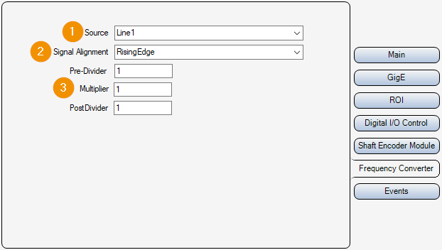
Source: Input or source for the frequency converter.
Signal Alignment:
RisingEdge: Rising Edge
FallingEdge: Falling edge
Signal Converter Parameters: The frequency converter has three modules which are applied one after the other (divider -> multiplier -> divider).
Pre-Divider: Factor by which the input frequency is reduced.
Multiplier: Factor by which the frequency is increased.
PostDivider: Factor by which the frequency is reduced.
Camera events
Camera events can be activated for analysis purposes. If an activated camera event occurs, the name of the event is written as ‘Warning’ in the ‘Gefasoft.MAK.Vision.GigEBaslerPylon’. log
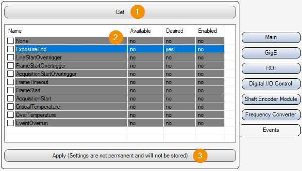
Get: Read event settings from the camera and update the list (2).
Event List: List of all Basler Pylon camera events.
Name: Name of the event.
Available: Indicates whether the event is available on the connected camera or not.
Desired: Indicates whether the user has tried to activate this event, regardless of whether it is available on the connected camera or not.
Enabled: Indicates whether this event is enabled.
Apply: Activates all events that are selected via the list checkbox (2). This setting is not permanent and is not saved. The events are only activated temporarily for analysis purposes.