Vision standard station
The majority of Viper.NET vision applications use the Vision Standard Station for communication with a PLC.
Digital handshake
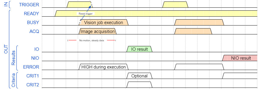
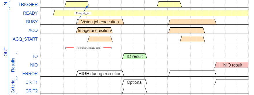
The Viper.NET standard handshake has been extended by specific bits for image processing. Depending on whether the cameras are controlled via software or hardware triggers, a slightly different handshake is necessary.
Software Trigger

ACQ: Is HIGH during image acquisition. After switching to LOW, a component can be transported to the next processing station, for example, and waited there for the BV result.
CRIT: See Criteria bits and user bits
USER: See Criteria bits and user bits
Hardware Trigger

If cameras are triggered externally, the parameter set must first be loaded and the camera started. Only then is the camera ready for image acquisition. The AQU_START bit signals to the PLC that all cameras are ready for an external trigger. ACQ and the CRIT and USER bits are used in the same way as for the software trigger.
Hint
The hardware trigger is used, for example, with line scan cameras with scan axes.
Configuration
<!-- ************************** -->
<!-- ***** Vision Station ***** -->
<!-- ************************** -->
<station id="1" name="BV 1"  type="VisionStation2">
  <param name="selectTgItemByTypeId" value="false"/>
  <param name="setBusyWithData" value="Auto"/>
  <handshake>
    <param name="wait4NegEdgeTriggerTO" value="-1"/>
    <in>
      <bit bitRef="1001" id="trigger"/>
    </in>
    <out>
      <bit bitRef="1001" id="ready"/>
      <bit bitRef="1002" id="busy"/>
      <bit bitRef="1003" id="error"/>
      <bit bitRef="1004" id="io"/>
      <bit bitRef="1005" id="nio"/>
      <bit bitRef="1006" id="acq"/>
      <bit bitRef="1007" id="acqStart"/>
      <bit bitRef="1101" id="crit"/>
      <bit bitRef="1102" id="crit"/>
    </out>
  </handshake>

  <commandInterface>
    <in>
      <data dataRef="07" offset="0" length="128" id="DATA"/>
      <data dataRef="07" offset="2" length="2" id="cmd" converter="System.Int16" converterParams="twistBytes=true"/>
      <data dataRef="07" offset="4" length="2" id="errCode" converter="System.Int16" converterParams="twistBytes=true"/>
      <data dataRef="07" offset="6" length="2" id="resCode" converter="System.Int16" converterParams="twistBytes=true"/>
      <data varRef="VarsVisionStation1.Type" id="type"/>
      <data varRef="VarsVisionStation1.ResetResultHistory" id="resetResultHistory"/>
    </in>
    <out>
      <data dataRef="08" offset="2" length="2" id="cmd" converter="System.Int16" converterParams="twistBytes=true"/>
      <data dataRef="08" offset="4" length="2" id="errCode" converter="System.Int16" converterParams="twistBytes=true"/>
      <data dataRef="08" offset="6" length="2" id="resCode" converter="System.Int16" converterParams="twistBytes=true"/>
      <!--data dataRef="08" offset="8" length="2" id="type" converter="System.Int16" converterParams="twistBytes=true"/-->
    </out>
  </commandInterface>
</station>
The configuration is divided into Parameter, Handshake and CommandInterface.
Parameters
selectTgItemByTypeId: With
value="true"the selection of the ToolGroupItem is enabled viacommandInteface->type.setBusyWithData: According to the handshake, the result data and bits are valid as soon as BUSY is reset. This means that the other GInOut data should actually be set first and only then BUSY->LOW. However, if it is ensured that BUSY and the remaining data can be written consistently, a write cycle can be saved for clock time optimization and all output data can be written at once.
False: Separate write cycle for BUSY->LOW (data that cannot be written consistently).True: BUSY->LOW is set along with the rest of the data (Consistently writable data).Auto[default]: Viper.NET tries to find out if the data can be written consistently via the GInOut-hardware, and then usesTrueorFalseinternally as appropriate.
setAcquisitionFinishedOnExposureEnd:
False[Default]: ACQ is reset when the images from all cameras have finished being captured.True: ACQ is reset once all cameras are done with exposure (not supported by all image-sources).
Note
setBusyWithData refers only to the output data and bits defined in the station. The result data of ToolGroup Items is always updated directly.
handshake
The individual bits of the handshake are parameterized here. The bits must be created in GInOut. The bitRef attribute is used to reference the bits by their ID. The id attribute defines how the bit is used in the handshake.
Further optional bits can be defined in the handshake:
<handshake>
    ...
    <in>
      ...
      <bit bitRef="1002" id="reset"/>
    </in>
    <out>
      ...
      <bit bitRef="1008" id="warn"/>
    </out>
  </handshake>
in/reset: Can be set by the PLC to perform a reset of the station.
out/warn: Is set in addition to IO if the image evaluation returns a warning result.
Additional parameters are defined in the handshake:
wait4NegEdgeTriggerTO: Max. Wait time for TRIGGER->LOW in milliseconds. After expiration of the waiting time without TRIGGER->LOW an error is generated. A reset of the station is required before the next trigger.
CommandInterface
In the CommandInterface section, GInOut-data or GInOut-variables are referenced, which are necessary for the operation of the station.
Hint
The data should always be referenced via GInOut variables with varRef.
The following data IDs are supported in this station (see also Input data):
inDATA: Reference to the entire data area containing the trigger bit (currently necessary, will be omitted in the future).type: Int16 value for the selection of the ToolGroup itemresetResultHistory: Int16 value for resetting certain historical data1: Reset/delete items in imagebars of ToolgroupItem views.
outerrCode: Contains an error code if the station returns an ERROR instead of IO or NIO.type: Mirror of thetypefrom the inputs.
Possible error codes in errCode:
4 - StartError: E.g. if no ToolGroupItem was found for the requested
type.5 - AcquisitionError: Image acquisition error.
6 - RunError: Run error, e.g. if a pattern or edge search fails and subsequent evaluations cannot be performed.
7 - CalibrationInvalid: Calibration invalid (see Calibration TG Item).
9 - InvalidLicense: No Viper.NET automatic license.
10 - Cancelled: Job was canceled.
Selection of the ToolGroup item
A PLC can decide at the trigger which toolgroup item or which test task is to be executed. Two options are available for this.
Option 1: ToolGroup Item ID
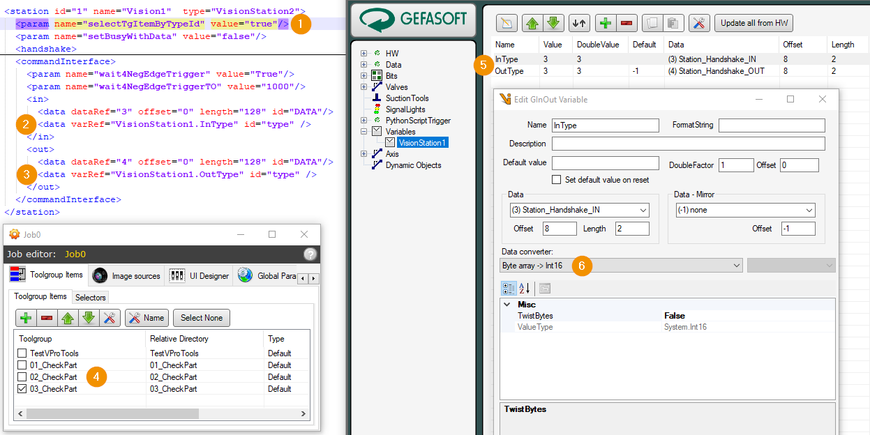
In the station.xml the option selectTgItemByTypeId can be activated for each station and the tag type can be linked to a GInOut variable under commandInterface/in/data. The PLC can now set the ID of the ToolGroup item as type in the trigger.
Only ToolgroupItems with an ID prefix can be selected with this method (see also Name and ID).

selectTgItemByTypeId: ‘True’ -> option enabled. ‘False’ -> option disabled.
in/type: Name of the GInOut variable with the default type ID.
out/type: Name of the GInOut variable into which the type ID used is to be written back.
List of ToolGroupItems: See also ToolGroup Items.
In/Out Type: Configuration of the type variable GInOutVariablen in the HW Explorer.
In/Out Type Data converter: The station data must be converted to an Int16 (16-integer signed value).
Option 2: ToolGroup Item Selector
For each job, a Selector can be activated and parameterized in the Job-Editor. The selector is executed by the vision station on trigger and selects the ToolGroupItem to be executed based on the value of GInOutVariables.
Hint
If VPP selectors are to be used, selectTgItemByTypeId must be deactivated in the station.
Criteria bits and user bits
Criteria bits can optionally be configured for a station, which are assigned to one or more DataAnalysis terminals in the ToolGroup Item Editor. For NIO components, this allows the PLC to categorize the fault. The CRIT bits are reset at BUSY-HIGH and set at BUSY-LOW.
Furthermore, USER bits can be defined, which are also reset on trigger or on station reset. They can be set, for example, in the sequence via Python scripts or the CommandInterfaceTool. They have no further meaning for the handshake.
Example of a configuration with CRIT and USER bits:
<!-- ************************** -->
<!-- ***** Vision Station ***** -->
<!-- ************************** -->
<station id="1" name="BV 1"  type="VisionStation2">
  <param name="selectTgItemByTypeId" value="false"/>
  <param name="setBusyWithData" value="Auto"/>
  <handshake>
    <param name="wait4NegEdgeTriggerTO" value="-1"/>
    <in>
      <bit bitRef="1001" id="trigger"/>
    </in>
    <out>
      <bit bitRef="1001" id="ready"/>
      <bit bitRef="1002" id="busy"/>
      <bit bitRef="1003" id="error"/>
      <bit bitRef="1004" id="io"/>
      <bit bitRef="1005" id="nio"/>
      <bit bitRef="1006" id="acq"/>
      <bit bitRef="1007" id="acqStart"/>
      <bit bitRef="1101" id="crit"/>
      <bit bitRef="1102" id="crit"/>
      <bit bitRef="1103" id="user"/>
      <bit bitRef="1104" id="user"/>
    </out>
  </handshake>
  ...