Area Inspect Tool
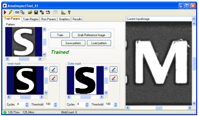
Similar to the AdvancedPrintInspectTool, the AreaInspectTool is mainly used for the inspection of defects in printing. It is better suited for large-area structures, since the edge area of the structure can be masked out and thus no apparent defects, e.g. due to frayed print edges, are detected.
Unlike the AdvancedPrintInspectTool, only one inspection is performed here.
Searching for the letter in the image
Positioning of inner and outer mask
Defect analysis in the letter using the inner mask. The outer mask can be used by subsequent tools to inspect the area, e.g. for ink residues around the structure.
The AreaInspectTool currently evaluates dark spots on bright structures with a blob analysis. A combination of intensity (grey value) and size is always used as a limit value. Two limit values can be specified in order to detect, for example, small, very dark defects, but also large, lighter defects such as impurities or color defects.
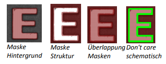
The two masks create a so-called “Don’t care” zone in which no check is performed. The “Don’t-care” zone for an ‘E’ is shown schematically below:
Records
Current.InputImage: The current input image. Also displays the search regions. Here you can set the search region of an inspection where a user-defined search range is used
Current.ReferenceImage: The reference or training image.
Current.InnerMaskImage: The current input image with the inner mask as an overlay graphic.
Current.OuterMaskImage: The current input image with the outer mask as an overlay graphic.
LastRun.InputImage: The last checked input image. Visualization of search regions, errors, etc.. Errors are always displayed in red. A red search region means that the inspection was not completed because, for example, the structure was not found.
Tab Train Params
On the left side in the tab “Train Params” the mask images are shown. The masks can be generated automatically and edited manually.
The automatic generation is carried out by clicking on the “Train” button. For this purpose, the current training image (top left under “Pattern”) is binarized and then the white area is cyclically reduced (Inner mask) or enlarged (Outer mask). The binarization threshold is set under the mask image using the Threshold parameter. The Cycles parameter specifies how often the white is dilated or eroded.
If the masks have not been generated sufficiently well, they can be changed via the two buttons to the right of the respective mask display. In the mask editor, the mask is always edited via an overlay. Either the old mask image (first button with grey background) or the current input image (second button with pink background) is displayed in the background.
The mask can be changed via simple tools like brush and paint bucket similar to known image editing programs. On the left side the tool as well as the color can be selected. The red overlay color becomes black in the mask image, transparent becomes white. A click on OK accepts the mask, Cancel discards the changes.
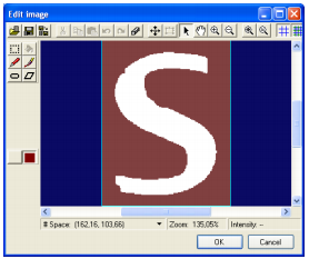
Mask editor with current mask
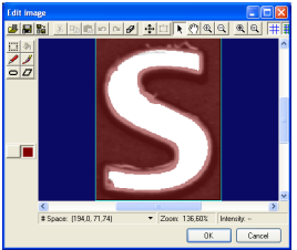
Mask editor with input image
Tab Train Region
Sets the training region. The training region is set in Current.ReferenceImage and should only contain the structure to be examined. The region functionality is analogous to the Cognex VisionPro standard.
Tab Run Params
Sets the search region that is set in Current.InputImage. The region functionality is analogous to the Cognex VisionPro standard.
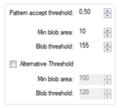
Pattern accept threshold: Threshold value for searching the structure (a PMAlign tool is executed in the background)
Min blob area: Minimum size of a blob in pixels.
Blob threshold: Gray value from which a pixel enters the error calculation.
Alternative Threshold: Activates the second threshold value mentioned above.
Tab Graphics
Error graphics: Results of the blob analysis
Region graphics: Graphics of the search region and the masks. The records “Current.InnerMaskImage” and “Current.OuterMaskImage” are only created if “Mask” is selected.
Results:
Contains the result list of the blob analysis.