AT 3D Sensor C6
Before a C6 series 3D laser sensor from Automation Technology can be used, the “CommonVisionBlox CameraSuite Runtime (x64)” from Stemmer Imaging must first be installed. This includes the “siNetFilter GigE Vision Filter Driver” filter driver, which is required for image acquisition.
According to the documentation, the following network settings must be set on the adapter:
Jumbo Frames/Packets: 9014 Bytes
Receive Descriptors/Buffers: 2048 Bytes
Transmit Descriptors/Buffers: 2048 bytes
Flow Control: Disabled
Interrupt Moderation Rate: Extreme
General settings
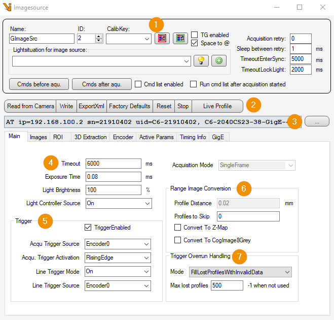
General settings: Image Source Editor
Function buttons:
Read from Camera: All GenICam parameters used are read from the 3D sensor.
Write: All GenICam parameters used are written to the 3D sensor.
ExportXml: All current AT parameters are read out and saved in an xml file.
Factory Defaults: Resets the settings of the 3D sensor to the factory settings.
Reset: Resets the settings of the 3D sensor to the parameter set that was active when the sensor was switched on.
Stop: Performs a manual stop of the acquisition.
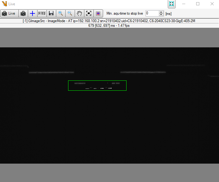
Live Profile: Shows the live image of the 3D sensor.
Camera list: Selection list of all C6 scanners. The list can be updated with the “… - Button” to update the list.
Sensor and light settings:
Timeout: Timeout for image acquisition in [ms].
Exposure Time: Exposure time during image capture in [ms].
Light Brightness: Brightness of the laser in [%].
Light Controller Source: Trigger setting for the laser line.
Acquisition Mode: Currently only the SingleFrame mode is supported.
Trigger:
TriggerEnabled: Activates the acquisition triggers used.
Acqu Trigger Source: Uses the selected internal or physical input signal as the trigger source for the AcquisitionStart.
Acqu Trigger Activation: Specifies which signal edges are to be used as trigger signals.
Line Trigger Mode: Activates the LineScan.
Line Trigger Source: Uses the selected internal or physical input signal as the trigger source for the LineStart.
Range Image Conversion:
Profile Distance: Distance between two profiles in [mm].
Profiles to Skip: Number of recorded profiles to be skipped for the Cognex image.
Convert To Z-Map: The AT image is no longer retrieved directly from the device buffer. The Z-Map is calculated via the scanner calibration and the AT image is then extracted from it.
Convert To CogImage8Grey: Converts the captured 16-bit range image into an 8-bit gray value image.
Trigger Overrun Handling:
Mode: Here you can set how a trigger overrun should be handled.
Max lost profiles: Number of profiles for which a trigger overrun is accepted.
Image components
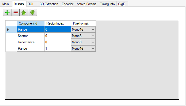
In contrast to AreaScan (intensity component only), it is possible to record more than just one image component in LineScan3D recording mode. Here you can define which image components are to be output for each region. Possible options are
Intensity
Range
Reflectance
Scatter
SumOfIntensity
Regions Of Interest
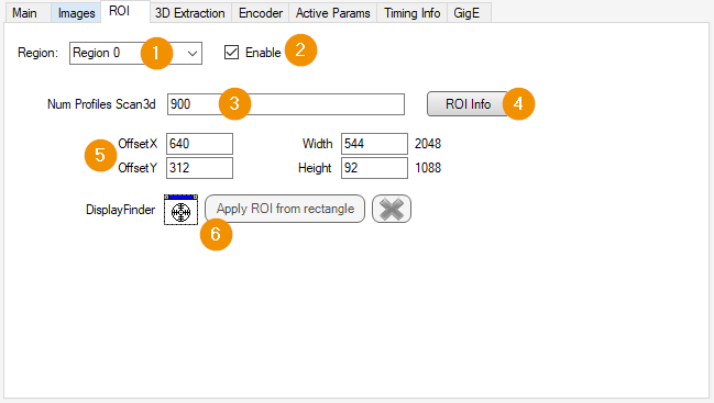
Region: Selection of the region whose settings are to be adjusted.
Enable: Activates the currently selected region.
Num Profiles Scan3d: Number of profiles to be recorded during the next image capture.
ROI Info: Help for setting an ROI.
ROI Settings: Offset and size of the current ROI.
Apply ROI from rectangle: Here you can drag a rectangle into the live profile, adjust it and apply its offset and size to the currently selected region.
3D extraction
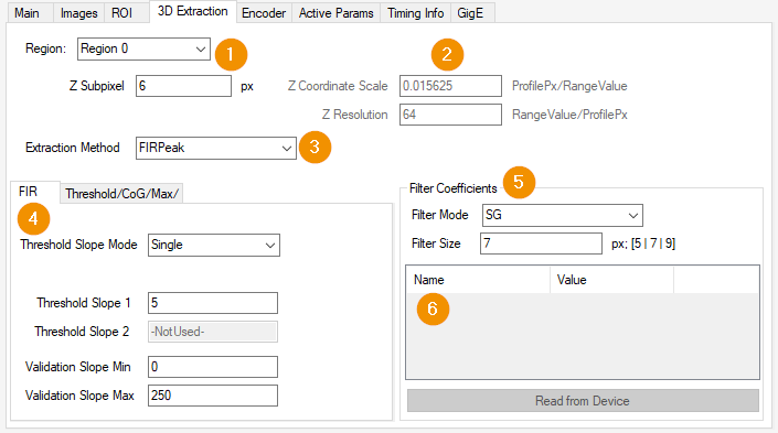
Region: Selection of the region whose settings are to be adjusted. This field is linked to the selected region on the “ROI” tab.
Z Coordinate Scale: Scaling factor for transforming a pixel from relative coordinates to world coordinates. [Formula: Scale factor = 1/(2^SubPixel)]
Z Resolution: Reciprocal of the scaling factor.
Z Subpixel: Subpixel scaling. Depending on the range algorithm settings used, the range values are scaled with the number of subpixels.Extraction Method: Selection of the algorithm used for precise extraction of the laser line position.
Extraction Settings: Parameters for the various extraction algorithms can be set here.
Filter Coefficients: Depending on the algorithm used, different filter types with the orders 5, 7 or 9 can be used.
Manual: If the “Manual” filter type is selected, user-defined filter coefficients can be used here.
Encoder
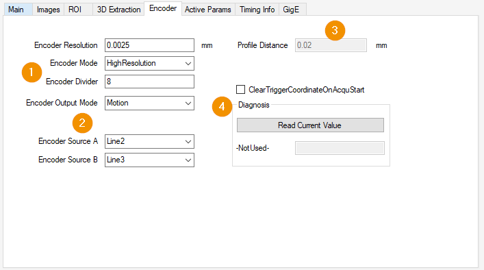
Encoder Control:
Encoder Resolution: The resolution of the encoder of the axis used must be entered here.
- Encoder Mode:
High Resolution: Each change of state of the encoder signal(s) is counted.
Four Phase: Each state must be run through once to increase the encoder value.
Encoder Divider: Specifies how many encoder increments/decrements are required to generate an encoder output signal.
- Encoder Output Mode:
Position Up: An encoder signal is only generated for movement in one direction. If the last encoder value of the recording is crossed in the opposite direction, the recording is only continued when the last recorded position is crossed.
Position Down: Like “Position Up”, but in the opposite direction.
Direction Up: An encoder signal is only generated for movement in one direction. The difference to “Position Up” is the position dependency.
Direction Down: Like “Direction Up”, but in the opposite direction.
Motion: Encoder output signals are generated in both directions.
Encoder Sources: Defines the trigger signal source(s).
Profile Distance: Distance between two profiles in [mm].
ClearTriggerCoordinateOnAcquStart: Provides the option to perform an EncoderReset before each image acquisition.
Read Current Value: Reads out the current encoder value of the currently used encoder.
Active parameters
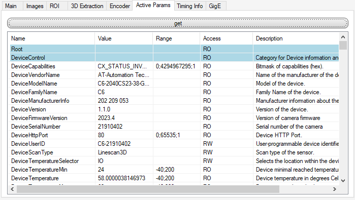
get: Reads all currently available GenICam parameters from the 3D laser sensor and outputs them in a list.
Timing Info
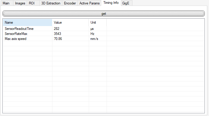
get: Reads the SensorReadoutTime(current time required to output an image) and the SensorRateMax(current maximum frame rate) from the 3D laser sensor and calculates the maximum traversing speed of the axis in [mm/s], without the effect of a trigger overrun.
GigE
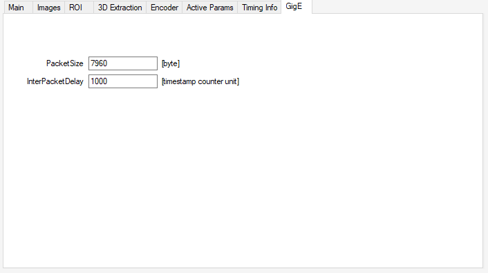
PacketSize: Specifies the packet size in bytes. The default value is 1500. If the network card supports jumbo packets/frames, the maximum value of 7960 bytes should be used.
InterPacketDelay: Specifies the delay between packets in [timestamp counter unit]. Default values are 100 or 1000.
Image source configuration
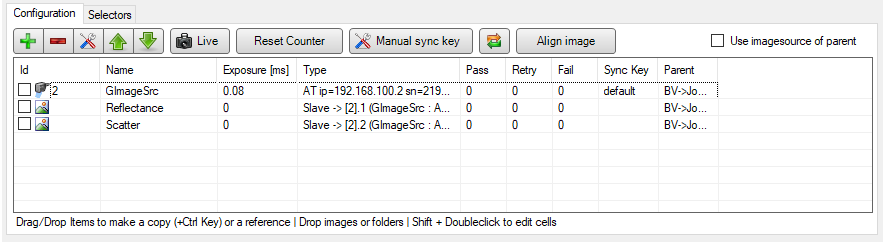
When extracting multiple image components, a slave image source must be created and configured for each additional image.